

Components of Pneumatic Conveying for Graphite Lumps
When it comes to the efficient and reliable transport of graphite lumps via pneumatic conveying systems, understanding the key components that make up this technology is essential. The process involves a series of interconnected elements designed to handle the unique properties of graphite, ensuring safe and effective material movement. As a leading provider of material handling solutions, Shandong HeadPowder Engineering Co., Ltd. specializes in designing and manufacturing pneumatic conveying systems tailored to the specific needs of industries that handle graphite, such as refractory, battery, and lubricant manufacturing.
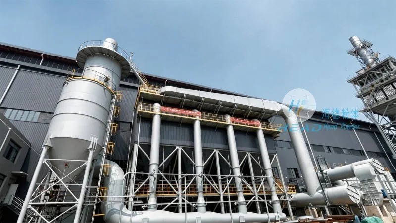
Key Components of the Pneumatic Conveying System
The pneumatic conveying system for graphite lumps typically consists of several critical components that work in harmony to achieve the desired transport. These components are engineered to manage the flow, pressure, and material characteristics of graphite, which can vary in size, density, and moisture content. The primary elements include the material feed hopper, the conveying line (either positive or negative pressure), and the discharge equipment.
Firstly, the material feed hopper is a crucial component that stores and feeds the graphite lumps into the conveying system. This hopper is designed to handle the bulk storage of graphite and ensures a consistent flow of material into the system. It often includes features such as a level indicator and a discharge valve to control the feed rate, preventing overloading or underfeeding that could disrupt the conveying process. The design of the hopper is tailored to minimize material degradation and maintain the integrity of the graphite particles, which is vital for applications where the material's quality is paramount.
Secondly, the conveying line is the core of the system, responsible for transporting the graphite lumps through the air. This line can operate under either positive or negative pressure, depending on the specific requirements of the application. Positive pressure systems use a blower or compressor to force air and material through the line, while negative pressure systems use a vacuum to draw the material and air into the line. The choice between these two depends on factors such as the distance to be covered, the volume of material to be conveyed, and the need to minimize dust emissions. The conveying line is typically made of materials resistant to corrosion and abrasion, as graphite can be abrasive and may contain moisture that could cause wear over time. Proper insulation may also be used to prevent condensation and maintain consistent air temperature, which is important for maintaining the quality of the graphite.
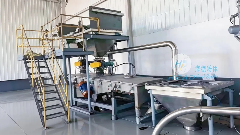
Thirdly, the discharge equipment is responsible for releasing the graphite lumps from the conveying line at the destination point. This equipment can include a discharge hopper, a rotary valve, or a pressure vessel, depending on the downstream process requirements. The discharge system must be designed to handle the material's flow characteristics and prevent blockages or spillage. For graphite, which can be fine or have a tendency to stick together, the discharge equipment may include features such as vibration or air knives to ensure smooth release. The discharge point is often integrated with a dust collection system to comply with environmental regulations and maintain a clean working environment.
Role of the Air Handling Unit
Another critical component in the pneumatic conveying system is the air handling unit, which includes the blower or vacuum pump and associated controls. This unit is responsible for generating the necessary air pressure or vacuum to move the graphite lumps through the conveying line. The selection of the air handling equipment depends on the system's capacity and the specific conveying method used. For example, a high-capacity system may require a large blower with a high airflow rate, while a low-capacity system may use a smaller vacuum pump. The air handling unit is also equipped with controls to regulate the pressure and flow, ensuring that the system operates within safe and efficient parameters. These controls may include pressure sensors, flow meters, and safety valves to prevent overpressure or underpressure conditions that could damage the equipment or cause material spillage.
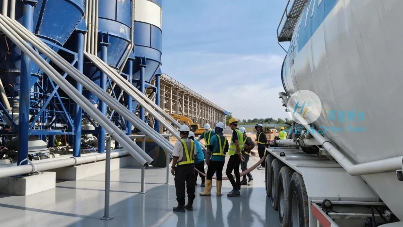
Material Handling and Safety Features
In addition to the core components, the pneumatic conveying system for graphite lumps includes several material handling and safety features that are essential for its operation. These features are designed to ensure the safe and efficient transport of the material while minimizing the risk of accidents or equipment damage. One such feature is the dust collection system, which is integrated with the discharge equipment to capture any airborne particles and prevent their release into the environment. This system typically includes a filter or cyclone to separate the dust from the air, which is then cleaned and recycled or disposed of according to local regulations. The dust collection system is crucial for maintaining a clean and safe working environment, especially when dealing with fine graphite particles that can be harmful if inhaled.
Another safety feature is the pressure relief valve, which is installed in the conveying line to prevent overpressure conditions that could cause the system to rupture or release material uncontrollably. This valve is designed to open at a specific pressure level, releasing excess air and preventing damage to the equipment or injury to personnel. The system may also include a check valve to prevent backflow of material or air, ensuring that the conveying process is unidirectional and preventing contamination or mixing of materials from different sources.
Integration with Downstream Processes
The pneumatic conveying system for graphite lumps is often integrated with downstream processes, such as mixing, compounding, or packaging, to form a complete production line. The discharge equipment is typically connected to the next process unit, ensuring a smooth transition from conveying to processing. The integration of the system with downstream processes requires careful consideration of the material's flow characteristics and the requirements of the subsequent equipment. For example, if the graphite is being used in a mixing process, the discharge hopper may be connected to a mixer with a specific feed rate, ensuring that the material is added at the correct time and in the right quantity. The integration also involves coordinating the speed of the conveying system with the downstream process to maintain a consistent flow and prevent bottlenecks or overloading.